Rage Against the Maschine
I have a Native Instruments Maschine Mikro (pictured below):

The box itself and the software that come with it are great but I’ve always felt like I could use it for more than just music. In this post, I will be describing how I reverse engineered the Native Instruments interprocess communication (IPC) protocol in order to liberate the Mikro (MK2). Let’s get to it!
Recon
As with most reverse engineering, it’s unclear where to start. For this project, I determined that a good place to start would be with the drivers. Since the MK2 is a hardware device, it makes sense that Native Instruments would want to write their own drivers to interface with the device. Looking in Library/Extensions, we can see that there is a kext titled NIUSBMaschineController.kext. Huh, looks like a promising lead. Let’s open up its Info.plist to see what it reveals to us.
If we look under IOKitPersonalities key, we see:

Not surprisingly, the MK2 is registered as an IOUSBDevice. We even get its product and vendor ID’s.
If we plug the MK2 in and run ioreg, we can see that the USB device exposes two USB interfaces:

An HID (human interface device) and a DFU (device firmware upgrade) interface. We’ll just be concerned with the HID interface since that would be the interface that button commands are sent through.
Opening the USB Interface
Let’s try to get a handle to the HID USB interface to see if we can read data from it.
We’ll follow the guide at https://developer.apple.com/library/archive/documentation/DeviceDrivers/Conceptual/USBBook/USBDeviceInterfaces/USBDevInterfaces.html#//apple_ref/doc/uid/TP40002645-TPXREF101, specifically Listing 2–8.
Running the code, everything works fine until the call to, USBInterfaceOpen. If we look at the IOReturn error code from the call, we always get code 0x2C5. Looking at the ioreturn.h header, we can see that this error code corresponds to the kIOReturnExclusiveAccess error. It looks like another process has already opened our USB interface!
Finding the Owning Process
There is likely a better way to finding the process that has our interface open, but I’ll describe the steps I took because it appropriately describes the messy reverse engineering process.
There are many different steps that could’ve been taken here. The one I decided to take was to search the Maschine 2 binary for strings related to certain words I thought might be related to the driver or the device itself.
Searching for strings containing the word “hardware” reveals a very interesting string:

It looks like the Maschine 2 application opens a program called the NIHardwareAgent. Let’s take a closer look at this hardware agent.
If the hardware agent is truly the program that has seized our USB interface, then it should probably have some strings with the word “USB” in them. Searching for such strings reveals the following:

Looking at the function where this string is used,
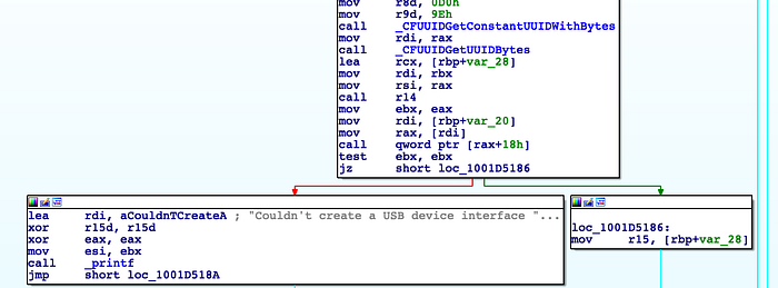
it looks very similar to the sample code Apple provides in Listing 2–8:
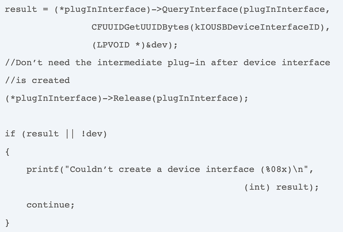
Therefore, we can be fairly confident that the Apple sample code was copy-pasted into the hardware agent and that this indeed is the process that exclusive access to the USB interface.
Inspecting the Hardware Agent
Looking at the function in the Maschine 2 binary that calls open '/Library/Application Support/Native Instruments/Hardware/NIHardwareAgent.app,
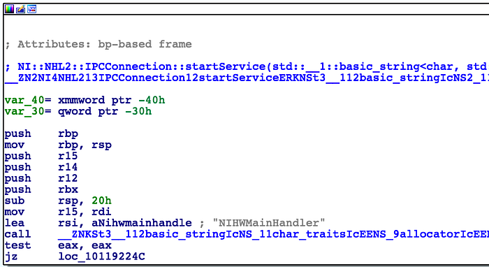
we can see that it is in the function IPCConnection::startService and contains the string NIHWMainHandler. This is a pretty good indication that the Maschine 2 app and the hardware agent communicate through IPC and using the port NIHWMainHandler.
Searching through the hardware agent binary, we find that one location this string is referenced is in a function named MessageSendPort::sendMessageToConnectionPort:

Looking at the functions called from this function, we eventually land on a function named IPCPort::OSImpl::sendMessage, which contains the following code snippet:
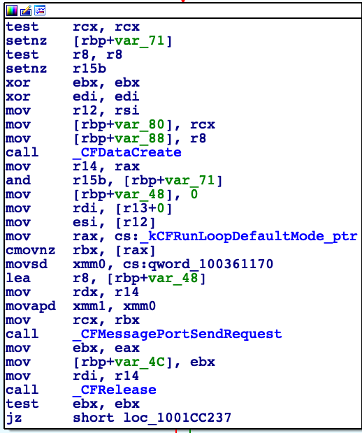
Aha! We can now see that the hardware agent and the Maschine 2 application are using CFMessagePort's for interprocess communication. Using our trusty HookCase, we can now hook the CFMessagePort send and receive functions to observe the data being passed back and forth.
Sniffing the Messages
We want to be able to see the IPC messages coming to and from the hardware agent. To observe the outgoing messages, we will simply hook the CFMessagePortSendRequest function. To observe incoming messages, we will have to make use of HookCase’s new dynamic hooking functionality.
This is because the function to create a receiving message port, CFMessagePortCreateLocal, takes a callout parameter. This callout is called when a message is received on the port and is passed a CFDataRef which points to the passed message.
Therefore, we can hook CFMessagePortCreateLocal and then hook the address specified by the callout parameter that the caller passed.
If we run the hardware agent with our hooks and open up the Maschine 2 GUI, we get the following output:
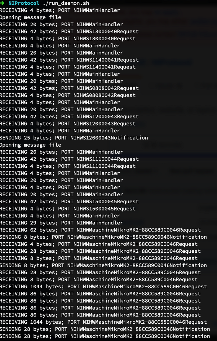
Here, in the callout receive hook, we print out how many bytes we received and on what port. We also write the received data to a file.
In the send hook, we again print out how many bytes are being sent and on what port and write them to a file.
Running the setup multiple times results in the same port names, so the numbers in the NIHWS{#1}{#2}Request and NIHWS{#1}{#2}Notification are not randomized (or at least the RNG seed is constant).
Looking at the #2 number in the port names, it increments from 40 by one with each new port name. Therefore, we can infer that this number is some sort of iteration counter.
We can also confirm that the 88CC689C string in the later port names is the serial number of my Maschine MK2. Therefore, we can infer that at some point during the setup, the serial number is exchanged between the hardware agent and the GUI.
Now let’s take a closer look at the messages exchanged to fully understand the handshake.
Decoding the Handshake
Here are the first twelve messages sent to the hardware agent:
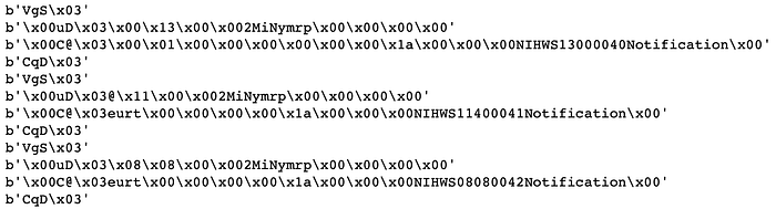
It looks like the incoming messages come in groups of four. First comes a four byte message (“VgS\x03”). Then there there is a 20 byte message that contains some interesting fields.
With some inspection, we can see that the second chunk of four bytes (0x0, 0x13, 0x0, 0x0 or 0x1300 in big endian) is the {#1} number used in the NIHWS{#1}{#2}Notification port name.
The next four bytes are the little endian int32 with bytes spelling out “NiM2”. I assume that this means “Native Instruments Maschine 2”.
The next four bytes are “prmy” which I assume means “pair my”. Therefore this message passes an ID for the new port name and the message “pair my Native Instruments Maschine 2”.
With this knowledge of how the messages are formatted, let’s again print out the handshake messages:

Here, we can see that each handshake iteration (from the GUI) side goes like:
- Send 0x3536756.
- Send 0x3447500, an ID for the next port name, ‘NiM2’, ‘prmy’, and 0.
- Send 0x3404300, 0x100 or ‘true’, 0, and the new notification (incoming to GUI) port name.
- Send 0x3447143.
After the fourth iteration of the handshake, the hardware agent sends some unknown information, the ID of the notification port it is sending to, and the serial number of the paired hardware device.
One peculiarity is the sixth iteration of the handshake when the port ID 0x1350 is sent, the rest of that iteration is not performed. This is not a fluke; it happens every time and I’m not sure why.
Finally on the eighth handshake iteration, the GUI sends the serial number it received from the hardware agent in the last field instead of 0.
Now that we’ve learned enough about the handshake to reproduce it, let’s analyze the messages sent from the hardware agent when different buttons are pressed on the device.
Decoding Button Presses
Here is screenshot of the messages sent from the hardware agent when the “1” and then “2” pads are pressed on the MK2:
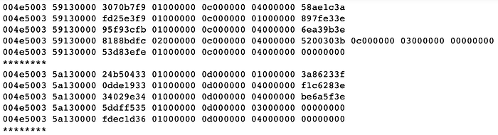
We can see that the field that changes in between button presses is the fifth. When the “1” button is pressed, it is set to 0xc or 12. When the “2” button is pressed, this field is set to 0xd or 13.
To confirm out suspicions, we can print out the same messages when pressing “5” and then “6”:

It is safe to assume that this field indeed encodes the button/pad number. The interesting thing to note, however, is that the mapping from the number on the MK2 to the number in this field is not the identity. It turns out that while on the MK2, the button numbers are layed out as:
13 14 15 16
9  10 11 12
5  6  7  8
1  2  3  4
They are encoded in the IPC messages as:
0  1  2  3
4  5  6  7
8  9  10 11
12 13 14 15
Therefore, we can convert from the button code in the IPC message to the interpretable MK2 number like so:
uint32_t code = <some code>, r, c, num;
r = code / 4;
c = code % 4;
num = (3 - r) * 4 + c + 1;
Putting it All Together
Now that we know how to perform the handshake with the hardware agent and parse the subsequent messages it send to us, we can implement the full solution to read from the MK2:
We can also use the information we have gained to act as the hardware agent and spoof messages from a fake MK2. Here is a demo of an iOS app I wrote that does just that (notice the instruments lighting up as the pads in the app are pressed):
Setting the Screen
While we have completed the main objectives of the project, it would still be nice to be able to control the screen and the buttons of the MK2 for a little flair.
Looking at the captured IPC messages after the handshake, we can see that there is an interesting message passed to the hardware agent:
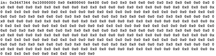
Note that directly after the field containing 0x400 (1024), there is an array of 1024 zeros. Therefore, a 1K array is being initialize to zero on the device. Looking a few messages in the future, we can see that a very similar message is again passed to the hardware agent:
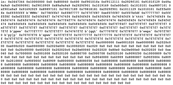
This time, it looks like that 1K array is being set to some unknown values.
It is clear that this array is interesting, but what could it correspond to on the device?
Thinking about the MK2 for a second, one realizes that it is actually just a box of buttons with some LED’s. There is no DSP or audio processing going on in the actual device. Therefore, what sort of data structure on the device would need 1K elements?
The answer, of course, is the screen. Let’s set this array with a sequence we would surely recognize on the screen and see if our hypothesis is correct. Setting the array with a repeating sequence of 0,0,0,0,1,1,1,…,255,255,255,255,0,0,0,0,…, we see the following sequence on the screen:
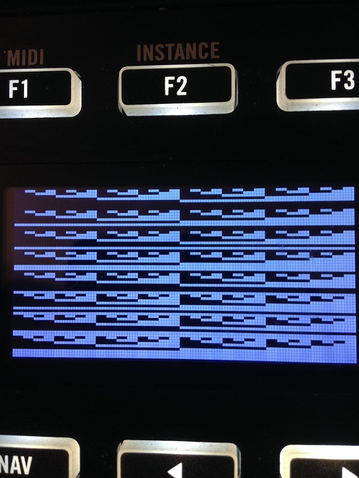
It looks like each bit of the screen’s 1K pixel buffer is mapped to 8 consecutive rows in the byte’s column. Therefore, we can control the screen data by converting a 128x64 8-bit grayscale image into a binary image and packing each band of 8 rows into bytes.
Setting the Buttons
Near where the screen data is sent to the hardware agent, we see some more interesting messages in TLV format (assuming the first field is the tag):

Here, the length of the array is 0x4e or 78. One guess as to what this array might control on the device is the button LED’s. Let’s count how many bytes should be needed to control the buttons and if this sums to 78.
We can count that there are 16 (pads) + 28 (control) = 44 buttons on the device. Alas, this doesn’t equal our target 78 so the search continues.
But wait! Each of the pads can display multiple colors so surely there are red, green, and blue LED’s! That totals 48 (RGB pads) + 28 (control) = 76 bytes. Damn! We’re still 2 bytes short.
Looking at the picture at the beginning of the article, we can see where the missing two bytes are: the “GROUP” button. Since the “GROUP” button is also RGB, we now have 48 (RGB pads) + 27 (control-GROUP) + 3 (RGB GROUP) = 78 bytes!
Let’s do what we did for the screen and set this array to a noticeable value and see if our suspicions are confirmed. Clearing the array then setting every other byte (starting with the first) to 255, we get the following sequence of LED’s on the device:
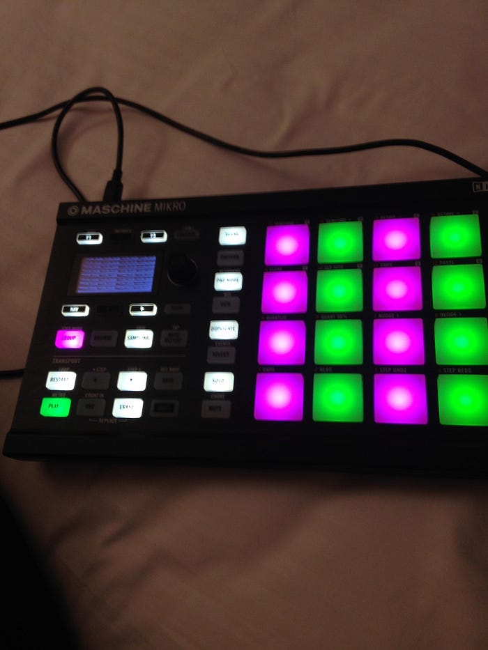
We can see that for the RGB buttons, successive buttons are colored purple and green. This is because two RGB pixels are lain out in memory as: red 1, green 1, blue 1, red 2, blue 2, green 2. With the pattern I set the button buffer to, this will be set to 255, 0, 255, 0, 255, 0. Therefore, the first button will be red + blue = purple (remember elementary school?) and the second button will be green.
Also note that the “PLAY” button is green. This is not because of the previous explanation. In fact, if you recall, the “PLAY” button is only controlled by 1 LED. It is just that the single LED controlling the “PLAY” button happens to be colored green!
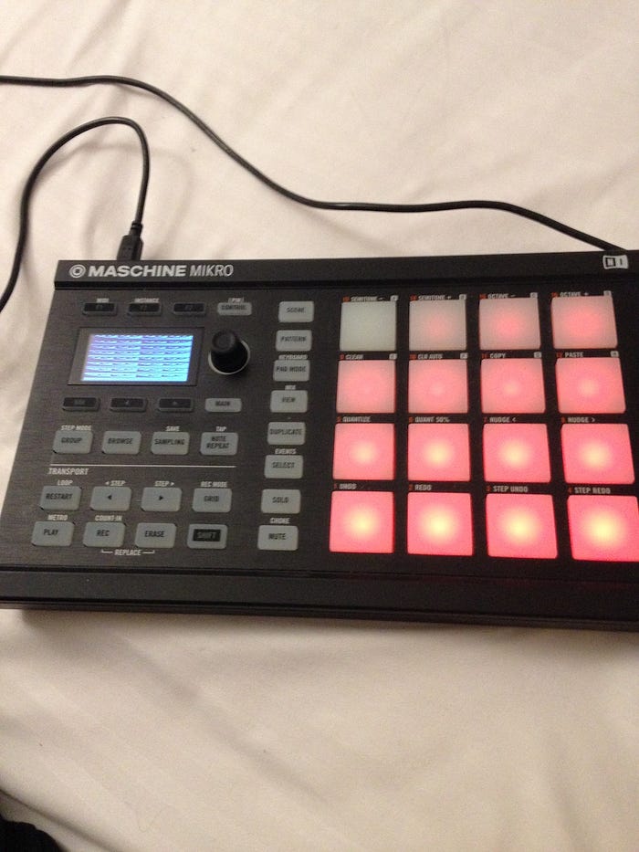
Now setting every other element as 255, starting with the second element, we get the following display:

As expected, the RGB buttons have switched colors. Again, note that the “REC” button is only red because the single LED lighting it up happens to be red.
It should be obvious, but just to be thorough, we don’t have to set pixel values to be either 0 or 255. We can employ some subtlety to obtain a nice gradient:
Conclusion
I hope you’ve enjoyed this deep dive into how the MK2 interfaces with your computer. The full code for reading from the hardware agent, acting as the hardware agent, and the iOS app for interacting with the custom hardware agent is available on my GitHub at: https://github.com/SamL98/NIProtocol.git
Thanks for reading!